
Function
Hydraulic oil returning from the circuit (R) passes through the filter element (1), is pressurized by a 0.5 bar check valve (2) and is supplied to the feed pump (S). Excess oil flows filtered over the integral check valve into the reservoir (T). As the feed pump is always fed with pressurized oil, the risk of cavitation is minimized and full performance is available even during the critical cold start phase.
An integral bypass valve (3) in the filter element (1) prevents too high back pressure (eg with cold start or contaminated filter element).
A bypass valve protection filter ensures that under no circumstances can unfiltered oil enter the feed pump.
A bypass valve protection filter ensures that under no circumstances can unfiltered oil enter the feed pump.
While with the use of separate filters, both circuits operate independently of each other, the combination of the two circuits through a suction return filter causes interaction between the circuits. By following the design criteria outlined below, you can take full advantage of the benefits provided by the suction-return filter concept.
Return flow required in the system
To maintain a precharge pressure of approx. 0.5 bar at the feed pump inlet, the return flow must exceed the suction flow under any operating conditions.
Allowable feed pump flow
- At rated speed and operating temperature, the fill pump volume flow should not exceed 80% of the filter rated volume flow rate (for example, with a return suction filter with a rated volume flow / return flow of 200 l / min, the volumetric flow of the filling pump should not be more than 160 l / min).
- In extreme cold starts (ν = 1000 mm² / s) and slightly increased idle speed.
(n = 1000 min-1), the volume flow of the filling pump must be ≤ 80% of the return flow.
Pressure loss in suction lines
Under the cold start conditions mentioned above, the pressure loss in the suction lines must not exceed 0.4 bar. This ensures that the fill pump is supplied with sufficient oil even with a partially contaminated filter element.
Back pressures in the system return lines
When draining oil from the hydrostatic drive is directed through the filter, allowable leakage oil pressures must be observed to protect the shaft seals. Here, in addition to the filter back pressure, the pressure loss caused by leaks from the oil pipes and the oil cooler must also be considered.
Depending on the application, the use of a cooler bypass valve is recommended.
Filter quality and oil cleanliness degrees
As standard, for all return suction filters, two ARGO-HYTOS filter grades are available: 10EX2 and 16EX2. Both with the patented EXAPOR®MAX2 design. The following oil cleanliness can be achieved according to ISO 4406:
- 10EX2: 18/15/11… 14/11/7
- 16EX2 20/17/12… 17/14/10
Los fabricantes de accionamientos hidrostáticos recomiendan principalmente para el funcionamiento normal una limpieza de aceite del 20/18/15 y a partir del 19/17/14 para mayores requisitos > Even with the fineness of the 16EX2 filter, these requirements are 100% met.
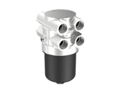
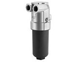
Online mounting
Until now, return suction filters have only been offered as a tank top mount version. As particularly with compact machines, the tank is often difficult to achieve, ARGO-HYTOS, as the only manufacturer to date, has developed return suction filters for in-line mounting. These in-line mounting versions can be integrated in an easily accessible location on the return line and the suction line.
|
E 068 / E 088 |
E 178 / E 258 |
|
|
Nominal flow |
up to 100 l/min, two length variants |
up to 250 l/min, two length variants |
|
Filter fineness |
10EX2 and 16EX2 |
10EX2 and 16EX2 |
|
Operating pressure, max. |
10 bar |
10 bar |
|
Bypass valve cracking pressure |
2.5 bar |
2.5 bar |
|
Bypass valve protection strainer |
mesh size 125 μm |
mesh size 200 μm |
|
Return connections |
G ¾ (1x) |
G1 (4x) |
|
Suction connections |
G ¾ (1x) |
G1 (3x) |
|
Tank connection |
G ¾ |
G1 |
|
Clogging indicator ports |
M12x1.5 (plugged) (2x) |
M12x1.5 (plugged) (2x) |